Quantcast
Channel: Cadence Digital Implementation Forum
Viewing all 1480 articles
Browse latest View live

trouble with auto routing minimum spanning tree, Layout XL

$
0
0

Hello,

I'm having trouble with virtuoso 6.1.7 layout XL auto-routing.

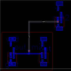
To show you my problem i created a hierarchical design consisting of two inverters in the first hierarchy, and a third inverter in the last hierarchy.  The structure should be visible in the image below: the big red square is the lower hierarchy, meanwhile on the top right i have the third inverter belonging to the higher hierarchy.

I would like the minimum spanning tree to wire the input of the third inverter to any positions of the blue line that connect the 2 inverters of the first hierarchy.

Since I am using the minimum spanning tree, I would expect the gray line to be the shortest, but instead the auto-routing is routing it to the pin i placed around the middle point of the horizontal blue line(that little blue square): in fact if I move the pin around the gray line follows it. I've tried using the layer generation tool to automatically cover the blue line with the blue metal pin, but the problem still occurs: the auto-route wire the net to that specific pin. I think that is because the auto-route consider that little blue square (the pin generated from the schematic) the terminal of the net.

How can i tell the auto-route that it can connect to any points of the blue line, and not just where i placed the pin generated from the schematic?

Right now the only solution i have to this problem is to flatten the layout, but i would prefer to avoid this solution and keep a hierarchical design.

Thanks

Best regards, Andrea


What is the command for opening the Xcelium Simulator ?

$
0
0

Hi All,

I have compiled and simulated my system verilog file using the command " xrun -64bit -sv ./up_counter.sv " 

I need to observe the simulations in GUI. what are the commands to open the simualator GUI?

Thanks,

Sandep.

Wreal Assign in for loop not working

$
0
0

Hi,

I have the below statements when given outside the forloop it works but within the forloop it does not

genvar i;

real b;

wreal a;

generate
for (i=0; i<20; i=i+1) begin
assign a = b;
end
endgenerate

Site Definition for Multi Height WB IO's

$
0
0

Hi,

I have to design LEF files for my IO's which are developed in our organization, My question is that we are having all WB IO's of different sizes(both X and Y), do I need to define different site definition for each size and then assign that IO's site to it?

If there is something else needed purely on LEF site, please let me know.

Thanks

Utkarsh

Add Power Ring above Core. Innovus

$
0
0

Hi,

I'm working on an ASIC that cointains pixels where each pixel has half area for Analog part and half Area for Digital part.

I would like to know if for the digital part is possible to create the power ring of each pixel above the core using Innovus instead of having around the core.

And also if you have any other suggestion on how to create the power planning for a Pixellated circuit in Innovus will be very useful.

Thank you

Regarding to LUP.6 Error in DRC for digital circuit P&R

$
0
0

Hello everyone 
Could you please help me to find out why this DRC.LUP.6 error appears in my layout design. ( kindly see the photo)

I am designing Read out circuit . 
RTL code implemented in verilog using Vivado design suite. 
I am using SoC Encounter- TSMC.180 nm for P&R , there is no any connectivity or geometry violations when I make verification in encounter. 
exporting the gds library to Vortuoso to check the DRC and LVS errors , then this error appears . 
please , help me to solve it. 


ERROR Description 

LUP.6 { @ Any point inside NMOS source/drain space to the nearest PW STRAP in the same PW <= 30 um
@ Any point inside PMOS source/drain space to the nearest NW STRAP in the same NW <= 30 um
@ In SRAM bit cell region, the rule is relaxed to 40 um
PACT_CHECK_NON_SRAM NOT NSTP_OS
PACT_CHECK_SRAM NOT (NSTP_OS OR NSTP_OS_SRAM)
NACT_CHECK_NON_SRAM NOT PSTP_OS
NACT_CHECK_SRAM NOT (PSTP_OS OR PSTP_OS_SRAM)
}

purpose of preCTS stage & latency/skew setting

$
0
0

Hi,
I have a question about the purpose of the preCTS stage.
preCTS stage is for drv fixing (max cap/tran/fanout..), also for HFNs optimizations.
But why it’s needed to specify estimated clock latency and skew, as after CTS latency and skew value
becomes real and thereafter all the rest of implementation optimizations stages (postCTS, routeOpt,…) will cover the lack of the preCTS work ?.

CTS DRV OPT Issue

$
0
0

Hi Folks,

I'm Seeing below issue in my design . I do have mutiple power domains in my designs.

Fixing clock tree overload: ...20% ...40% ...60% ..**WARN: (IMPCCOPT-2348): Unfixable transition violation found at snps_clk_UPF_ISO {Ccopt::ClockTree::ClockLogic at 0x2b8633f7a860, uid:A4648b7, a gt04p00 at (2038.028,767.448) in powerdomain MMCX in usermodule module cp_wrapper in clock tree SCAN_CLK} driving net o_rsc_epcb_tx_clk. CCOpt is unable to add buffers due to a dont_touch constraint on a verilog module or module port.

**WARN: (IMPCCOPT-2342): Unfixable transition violation found at CLK<2> driving net CTS_2. CCOpt is unable to appropriately place buffers to fix this violation.

.**WARN: (IMPCCOPT-2342): Unfixable transition violation found at cpp_wrapper/placeFE_OFC38604_clk {Ccopt::ClockTree::ClockDriver at 0x2b859d01ffb8, uid:A46357b, a CTSG g_aoinvp5f06p00 at (948.686,626.832) in powerdomain XYZ/INT in usermodule module XYZ in clock tree SCAN_CLK} driving net CTS_259. CCOpt is unable to appropriately place buffers to fix this violation.

what could be the issue here , can any one elaborate  & how do i fix this violation.

Thanks.


generateCapTbl command fails in INNOVUS because "Poly layer is not defined in pcs file"

$
0
0

I am running the following command in INNOVUS:

generateCapTbl -ict <ict file> -output <captable file>

to convert a .ict file to a captable file. I am getting the warning: "IMPEXT-6014 error Poly layer is not defined in the PCS file, M1 will see substrate directly" followed by the Error "POLY height is not correct" and the Error "M1 height is not correct". I looked through my .ict file and it looks good, the poly layer has gate_forming_layer set to true, so I am confused as to why the poly layer isn't being recognized.

Content is the cornerstone of any digital strategy

$
0
0

First of all, it's important to understand that content marketing can serve as a complementary strategy to any other digital strategy. Its virtues are numerous since it helps your SEO on the web by increasing the authority of your domain, it is the main source of your communication campaigns on social networks and it encourages registrations whether to subscribe to a newsletter, obtain downloadable content, or simply leave a comment. It also improves the popularity of your webpage and other pages on your site. For any business, being present on the web through is essential but no longer sufficient today. Wikipedia page creation agency is also very important in order to maintain your business online. What do you think?

Hire the pro for some professionalism

$
0
0

The company website is the perfect domain to start with your business but when it comes to the profile building part, the "About Us" section may fall short of answers. What if there was something a lot better than just your web store? A Wikipedia page created by a professional Wikipedia writers is what nails the X-factor. It is a free website anyway so why not? A Wikipedia page is something that is clicked on 65% times more than any other link pooping up on Google so it's not just worth it, it is necessary to create one. Don't you agree? 102

Cannot apply preserve attribute in VHDL source file

$
0
0

Hello,

we are currently synthesizing a design that contains some triple modular redundancy and we want to keep Genus from throwing out whats redundant. So we tried to set the "preserve" attribute in our VHDL file. Putting it on instances gave us errors because it could not be applied to unmapped instances. Applying it to the signals in question did not change anything.

Then my collegue put the "preserve" attribute on the exact same signals through the "set_dont_touch" command in Genus and it worked perfectly fine.

So I am a bit confused now. Is it just impossible to set attributes in the VHDL source file or am I doing something wrong? I also checked that the attributes are read in my FPGA tool which I use to test the code. Of course it does nothing with that attributes, it uses its own, but it still reads and displays them. So the syntax seems correct.

Thank you in advance for any help

Genus Version is 17.22

**WARN: (IMPESI-429): No RC available on net xxx in INNOVUS 19.13

$
0
0

Hi,

during optDesign postRoute log show a lot of warning IMPESI-429, what could be the reasons? 

Which variables give us the H/W information of the Core?

$
0
0

Hi,

I am trying to develop a TCL script to automate the process of layout generation on Innovus.

In order to do precise placements of pin in the script, I need some variables to get the information about the height and width of the Core so that I can place them at precise locations through the script.

Instead of some hard coded information for the start and end points of pin placement, I would like to do something like in the second command which would depend on the Core dimensions.

editPin -fixOverlap 1 -spreadDirection clockwise -side Left -layer 3 -spreadType range -start 0.0 5.0 -end 0.0 500.0 -pin {{EEGIn[0]} {EEGIn[1]} {EEGIn[2]} {EEGIn[3]} {EEGIn[4]} {EEGIn[5]} {EEGIn[6]} {EEGIn[7]} {EEGIn[8]} {EEGIn[9]} {EEGIn[10]} {EEGIn[11]} {EEGIn[12]} {EEGIn[13]} {EEGIn[14]} {EEGIn[15]} clk}

editPin -fixOverlap 1 -spreadDirection clockwise -side Left -layer 3 -spreadType range -start 0.0 0.1*Height -end 0.0 0.9*Height -pin {{EEGIn[0]} {EEGIn[1]} {EEGIn[2]} {EEGIn[3]} {EEGIn[4]} {EEGIn[5]} {EEGIn[6]} {EEGIn[7]} {EEGIn[8]} {EEGIn[9]} {EEGIn[10]} {EEGIn[11]} {EEGIn[12]} {EEGIn[13]} {EEGIn[14]} {EEGIn[15]} clk}

Could anyone please suggest if there is a way to it?

Thanks,
Vinay

How to pass a string variable in the addRings command?

$
0
0

Hi,

I am trying to pass my metal layer information for the addRing command using some string variables. However, the console prints an error saying variable not found.

I am using the following command:

addRing -nets {VDD VSS} -type core_rings -follow core -layer {top $horzPowerLayer bottom $horzPowerLayer left $vertPowerLayer right $vertPowerLayer} -width {top 4 bottom 4 left 4 right 4} -spacing {top 1.8 bottom 1.8 left 1.8 right 1.8} -offset {top 1.8 bottom 1.8 left 1.8 right 1.8} -center 1 -threshold 0 -jog_distance 0 -snap_wire_center_to_grid None

Following is the log that I see on the terminal:
#% Begin addRing (date=02/04 02:06:12, mem=820.9M)
#% End addRing (date=02/04 02:06:12, total cpu=0:00:00.0, real=0:00:00.0, peak res=820.9M, current mem=820.9M)
can't read "horzPowerLayer": no such variable

The variables $horzPowerLayer and $vertPowerLayer are M7 and M6 in values respectively which are read through a file. The values hold well before the addRing command is executed but they are not recognized in the command itself. Can someone please let me know the right way to pass this information? I plan to do the same for the dimensions as well so it would be helpful if you could include that in your discussion as well.

Thank You
Vinay


Joules: rtlstim2gate-Flow

$
0
0

Hello together,

I'm wondering about the "-keep_libraries"-option of "rtlstim2gate" and why the dafault is to delete the Lib-information from elab-DB.

In following example I use rtlstim2gate WITHOUT "-keep_libraries"-option:

read_libs ...

read_hdl ...

elaborate ...

write_db -to_file elab.jdb

rtlstim2gate -init elab.jdb

read_db <some synthesized-design from genus>

read_stimulus stimulus.sdb

propagate_activity

compute_power -skip_propagation

Where the hack does compute_power gets its Lib-information get from, when rtlstim2gate deletes the Lib-informations?

Thanks and best regards

Markus

Path exceptions modeling for ETM

$
0
0

On page 3 of Hierarchical Timing Analysis: Pros, Cons,and a New Approach ,  how is set_output_delay related to set_multicycle_path here in this case ?
and how to re-code the path exceptions ?  Any examples ?

Why need to duplicate the ports for that MCP ?

Someone told me that another way to set path exception is by using set_case_analysis  ?

Path exceptions modeling

In certain situations, path exceptions must be re-coded for ETMs, e.g., when there are multiple output delays on a port and one of the output delays has a multi-cycle path (MCP) through one pin internal to the block. Unless one successfully preserves that internal pin (which increases the size of the model) or duplicates the ports for that MCP, design teams must create and manage exceptions to achieve the same timing result as flat analysis.

The expertise of a pro

$
0
0

A Wiki page is easy to create, so it may seem. Give it a try and you will know that's not true. Academic writing is one of the most challenging forms of writing and with all the research it takes, it is best left at a professional's behest. The site is free to access and create an account at but the rest, you have to invest for. A Wikipedia writing service expert will have your page published and running in no time and will be worth every bit of the money spent. A professional will know how to keep the content free from biases. A Wiki page needs to abide by certain guidelines. What do you think?116

Obtaining power traces using Cadence Virtuoso

$
0
0

Hi, all !!

I am a beginner with the Cadence tools. I have an algorithm, AES-128, written in Verilog. I wish to obtain the current traces of the AES circuit using Cadence Virtuoso. Can someone kindly guide me in this regard?

(The attached figure depicts the whole scenario.)

Power planning of har dmacros.

$
0
0

I Have a SOC design with switcheble domains (AON, PDSWC for CPU, PDSWM for MAC) and a hard macro RF transceiver (TRX using PDSWM power net for digital, PDSWA for radio with dedicated power port). 

The TRX is totally invisible to user and is in the form of a standard libary with verilog hehavioural, DB and GDS database. 

What are the proper UPF 1.0 or 2.x methodology to handle this Hmacro situation? 

Viewing all 1480 articles
Browse latest View live


<script src="https://jsc.adskeeper.com/r/s/rssing.com.1596347.js" async> </script>